
How does it work?
Objects in ABS possess sets of properties specific to that object. For example, a diffuser has a property for flow, a receptacle has a property for circuit number, and a sink has a property for fixture type. These properties can be assigned by the designer or extracted from the object or style, linked to the object by the tag and reported by a schedule. The best way to understand these relationships is to create a schedule from scratch.
Creating a basic schedule.
When creating a schedule, first determine what it is the schedule should report. For this example I will create a small diffuser schedule that reports the number of diffusers in a drawing, the diffuser type, and the diffusers flow.
Before creating this schedule, place some diffusers in a drawing and set different CFMs in them. Tag the diffusers to link the property set data to the diffusers so it can be released to the schedule. Unlinked data will result in schedule cells or properties being left blank or the schedule reporting “?”s. This is the schedules way of telling you that it knows the object is out there but it can’t read all of its properties.
Schedules, like other objects in an ABS drawing are controlled by a style. If you are familiar with a text style in AutoCAD, the same general premise applies. The text style is used to control the text height, width, and font of the text, the same way our schedule style will control the columns, content and look of our schedule.
To create a new schedule style, open the Style Manager by selecting it from the Format pull down menu. Schedule styles are found under the Documentation Objects heading of the current drawing. Select Schedule Table Styles, right click and then select New. This will open the new schedule table style for edit. There are 7 tabs in a schedule table style. Let’s start at the left and visit each tab that will define our schedule.
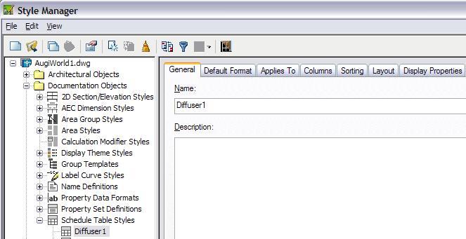
Start with the General tab and name this new style “Diffuser 1”. You may then supply a description if you like and attach any notes by selecting the Notes Button.
The Default Format Tab controls the text appearance and cell configuration of the schedule. Assign the text style, alignment, height, gap, and rotation here. There is a control Matrix symbol. This is used in matrix columns or if checked to denote true/false values. Cell size can also be controlled. For this example I will accept all of the default values in this tab.
The Applies To tab is used to filter the types of objects to schedule. Click the Clear All button to uncheck all the object types, then recheck “Multi-View Part”. Under Classifications select “Air Terminal”. This schedule will now only extract data from multi-view parts that are air terminals and ignore everything else.
The Columns tab is used to define what the column headings are and how the data below should be formatted. First check the Include Quantity Column check box. This will give us our first column header of Quantity. Next select the Add Column… button. This brings up the Add Column Dialog box. Properties that you can add as a column are sorted by the properties set they come from in the Categorized tab or alphabetically in the Alphabetical tab. In either tab select “Flow_CFM”. In the Column Properties area, change the Column Heading to “CFM”. Ensure the Data Format is Flow-CFM. You can change the cells properties if you like using the “Override Cell Format…” button. In the Column Position area select “Insert After” then QTY. This places the CFM column directly after the Quantity Column.

Next select the Add Column… button again. This time select “PD Part description”.
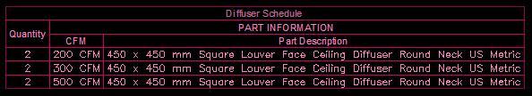
Select OK to insert the column in the last position. Now Select the Part Description column, hold down your “ctrl” key to also select the CFM column. With both columns selected click the Add Header... button and type “PART INFORMATION” to add a header over the CFM and Part Description columns.
The Sorting tab allows the user to define how the schedule rows will be sorted. Select the ADD button to choose a property to sort by. The sort order can be set by property to ascending or descending. Add more properties sub-sorting like first by CFM then by quantity. Properties are sorted starting from the top and going down. Use the Move Up and Move Down buttons to change the sort order.
The Layout tab supplies a place to define the table title or schedule name. It is also the place where overrides for text appearance and cell configuration of the title, column headers and matrix headers can be applied. I will make my table title “Diffuser Schedule” and set a different style for the title and column headers text by selecting the “Override Cell Format…” buttons next to them.

The Display Properties tab allows me to define color, visibility, layer and more for all parts of the schedule. Check the “Style Override” check box to open the Display Properties dialog box.
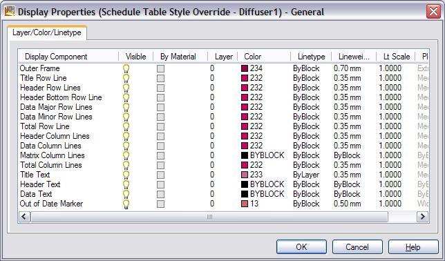
Select OK in the Display Properties dialog box, and APPLY and OK to close the Style Manager.
The schedule is now complete so let’s test it. One of the easiest ways to add this schedule to a drawing is to insert a standard schedule then change its style in Properties to the new schedule style. You can also drag the new style from the Style Manager to your palette. Once in the drawing, the new schedule can now be dragged into a palette for future inserting. A word of warning, If you were in Drawing1.dwg when you dragged the schedule to the palette and you later move or delete Drawing1.dwg, the palette tool will no longer function because it is only a link to the drawing where the style definition came from. A good practice is to only drag tools to a palette from a safe network or local drive that you are sure you will not accidentally move or delete.
One last piece of advice, don’t start from scratch if you can help it. Check the palettes and Content browser for any schedule that may be close to what you are trying to produce. Insert this schedule into a blank drawing. Select the schedule right click and pick Copy and Assign to create a copy of the original style that can be freely changed.
No comments:
Post a Comment