
In the AutoCAD world, layers are used to help control what and how entities are shown. More control has always meant more layers.
Display configurations in ABS simplify the situation by allowing the user to instantaneously set if and how objects are displayed with much finer control. Display Configurations allow users to view an object differently based off the requirements of the drawing. Examples include varying levels of hatch in a wall object depending on the anticipated plot scale. Figure 1 shows a single wall object with the three different display configurations of “Low Detail”, “Medium Detail” and “High Detail” applied to it.
 Figure 1
How does it work?
A Display Configuration is selected by the user
A Display Configuration is a collection of rules for all object types that defines how objects will be displayed (not lines, arcs and circles).
The Display Sets are enabled by the selected Configuration
A Display Set contains rules for all objects and is applied by view. (Model, Plan, Section/Elevation, Diagnostic) A Display Configuration can have several Display Sets associated with it.
Display Representations are enabled by the Display Sets
A Display Representation is a set of rules for a particular object that defines how that object will display.
A Display Set contains Display Representations for all object types and applies them to a view orientation.
This should make about no sense at all until you apply it by creating your own display configuration. Let’s create a display configuration for an electrical lighting plan in ABS to demonstrate these relationships. For this article I will only show how to configure a couple of objects, but the methodology is repeated for every object type required for any configuration.
Creating a Display Configuration
The Display Manager is used to create and control all aspects of a display configuration. From the Format pull down select “Display Manager”. To create our new configuration, select “Configurations” in the left hand window, right click and select “New”. Name this configuration “Acme Lighting”. Add a description of the configurations purpose. Apply the configuration. The configuration needs a set of representations to define how objects are displayed. Rather than create one from scratch, copy the standard electrical plan set by expanding the “Sets” folder and selecting “ABS Electrical Plan”. Right click and select “Copy”. Then right click and select “Paste”. Select “ABS Electrical Plan (2)” and rename to “Acme Lighting Plan”. See figures 2 and 3.
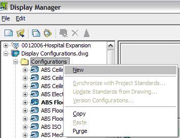
Figure 2 – Creating a new configuration.
Figure 3 – Copying a display set.
The “Acme Lighting Plan” set will contain the representations for objects when viewed in plan. Copy “Acme Lighting Plan”, paste it and rename it to create a new set for objects viewed in model named “Acme Lighting Model”. To assign these sets to the configuration “Acme Lighting”, select the “Acme Lighting” configuration on the left and the “Configuration” tab on the right. Select “Acme Lighting Plan” for the display representation set associated with the top view direction. See figure 4. Figure 4
Next, select “Acme Lighting Model” for the display representation set associated with the default view direction.
Now that we have a configuration that the user can select, and that configuration is calling view specific sets, it’s time to define how individual objects will represent themselves. Expand “Representation by Object” on the left of the Display Manager. A list of objects is displayed. Select “Ceiling Grid” from the list. Select the “Model” display representation for the “Acme Lighting Model” display set and the “Reflected Screened” display representation for the “Acme Lighting Plan” display set. This will show the ceiling grid screened in plan view and normal in a model view. See figure 5.
Note if you use “Plan Screened” your ceiling grid will remain invisible because in a normal plan view ceiling grids are off. This is perfect for a power plan, because the ceiling grid would be meaningless.
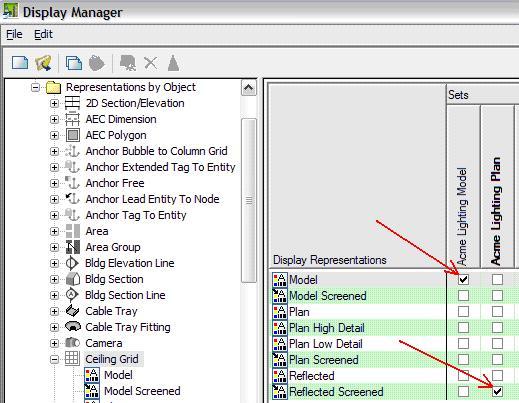 Figure 5
Let’s review all three components to defining a display configuration and their relationship’s to each other in the context of the configuration we just made.
Representations
Define how individual objects can look.
Ceiling grid objects have different representations. We selected “Reflected Screened” for when viewing our design in a top or view and “Model” for every other view.
Sets
A group of representations defined for a specific view.
We created two sets of representations called “Acme Lighting Plan” and Acme Lighting Model” We could now open a set and edit all of the representations within.
Configuration
A complete collection of sets required for the desired display of objects.
We created a Configuration called “Acme Lighting”. When selected it calls the appropriate sets which in turn selects the appropriate representations.
Test the new configuration by placing a ceiling grid in the current drawing. In figure 6 the SW isometric view shows a green ceiling grid and the Plan view shows a grey ceiling grid. This demonstrates that a single configuration provides view dependant control if set up correctly. Figure 6
More Practice
Now let’s set this configuration up to handle mechanical duct and diffusers. In a lighting plan, seeing the diffusers is critical, but the duct will only confuse the drawing. Open the Display Manager and expand “Representation by Object” on the left. Select “Duct” from the list. Select the “Model” display representation for the “Acme Lighting Model” display set and unselect every display representation from the “Acme Lighting Plan” set. See figure 7. With no display representation selected, duct will not appear in the “Acme Lighting” display configuration. Repeat with “Duct Custom Fitting”, “Duct Fitting” and “Duct Flex” to prevent all forms of duct work from showing up in your lighting plans.
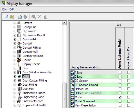 Figure 7
Diffusers are Mvparts, select “Multi-View Part” from the Representations by object list, and then select only the “2 Line Screened” display representation for the “Acme Lighting Plan” display set. Select only the “Model” display representation for the “Acme Lighting Model” display set.
Test the configuration by placing some duct and a diffuser into the current drawing. Figure 8 shows the results you should get in model and in plan views. Figure 8
The Display Manager
When you first get started with the Display Manager it can be confusing. Everything looks the same, yet it’s different. This is due largely to the fact that representations, sets and configurations are linked like box cars on a train. When navigating the Display Manager, no matter which portion you look at you can see the links to the rest of the train. When you select the “Acme Lighting” configuration in the Display Manager, you see the two sets associated with it and can access them directly from there.

The real secret is finding the view of this train that works best for what you are trying to do. As you advance in your use of the Display Manager, having the relationships of representations, sets and configurations so tightly integrated is a real advantage.
Creating a display configuration might take a lot of practice to really master, so be prepared to try this exercise a few times. I hope you find that it’s worth the effort.
No comments:
Post a Comment