
This article comes from my Revit Basics Blog which I have decided to shut down. It will help the beginner learn about making families by starting with a simple concept and progressively making it harder. It's not a light fixture, air handling unit, or custom sink, but it will put you on the path. Good luck!
In this example a bookcase family is required that a user can define the HxWxD. The number of shelves should be determined by the height, there should also be a control for the thickness of the material and the option to have doors on the bottom 3 shelves.
In this example a bookcase family is required that a user can define the HxWxD. The number of shelves should be determined by the height, there should also be a control for the thickness of the material and the option to have doors on the bottom 3 shelves.
To gain the type of control needed, the shelves will have to be nested into the bookcase family. Nesting means the shelves will be an independent family that will be loaded into the bookcase family.
Build the Shelf Family
1. Begin with the Generic Model.rft template.
2. Unpin the 2 references planes in the template and uncheck the Defines Origin check box.
3. Add 4 reference planes to define the length and width of the shelf in the reference view. Set the Right and Back reference planes to Define Origin and Pin them in place.

4. Name the new planes (Front, Back, Left, Right) and set the Is Reference parameter accordingly.
5. Use the Extrusion tool on the Home tab to create a form for the shelf, locking it to the 4 defining planes.

6. Use the dimension tool to dimension the Width and depth of the shelf form.
7. Select the width dimension and pick the Label: drop down on the Options Bar, and then select .

8. The Parameter Properties dialog appears. Fill it out as indicated below. Do the same for the Shelf Depth dimension.

9. Switch to the Front view and create a reference plane to define the top of shelf. Name the reference plane, set its reference to Top and lock the top surface of the shelf form to the plane.
10. Set the shelf’s thickness to ½”. Create a parameter for Shelf Thickness as was done with width and depth.
11. Save this family as A-Fn Bookcase-Shelf.rfa
Build the Bookcase Shell
1. Begin with the Generic Model.rft template.
2. Unpin the 2 references planes in the template and uncheck the Defines Origin check box.
3. Add 4 reference planes to define the length and width of the shelf in the reference view. Set the Right and Back reference planes to Define Origin and Pin them in place.
4. Name the new planes (Front, Back, Left, Right) and set the Is Reference parameter accordingly.
5. Add 3 more reference planes to define the thickness of the back and sides of the bookcase.
6. Use the Extrusion and trace the footprint of the bookcase sides and back. Lock the faces of the extrusion to the reference planes.

7. Switch to the Front view and create a reference plane to define the top of bookcase. Name the reference plane, set its reference to Top and lock the top surface of the shelf form to the plane.
8. Create parameters for Bookshelf Height, Bookshelf Width, Bookshelf Depth, and Bookshelf Thickness the same way parameters were added to the shelf family.
9. Add “half” parameters for the bookcase width and depth. These will be used to keep the center planes in the center.

10. Click the family types button to open its dialog.

11. Group the “half” parameters under constraints and insert the formulas below to ensure they are always half of their parent lengths.

12. This is a good time to flex the family by trying different dimensions in the parameters and checking that the geometry follows suit.

Add the Bottom Bookcase Shelf
1. Begin loading the shelf family into the bookcase family and place it off to the side in the reference level view of the bookcase family.
2. Use the Align tool to lock the sides of the shelf to the inside planes of the bookcase shell and the front plane.
3. Select the shelf to access its properties. Here we want to create links between the parameters in the shelf to new parameters in the bookcase to control the shelf’s width, depth and thickness.

5. Do the same for Shelf Width and Shelf Depth.
6. In the Family Type dialog we can now create formulas to keep the shelves the correct size as the case changes. Create the formulas shown in the image below.

Creating a Swappable Shelf
To add another level functionality (or complexity) we can add a parameter that will allow the user to switch from one type of shelf to another.
1. Open the original shelf family and save it as the second shelf option. The shelf below has extrusions added to the bottom.

3. In the Family Types dialog create a new Type parameter named “Swappable Shelf”. Make its discipline Common, its Type of Parameter


5. Select the original shelf in the bookcase family now. In the Properties dialog, look for the Label parameter and change it to “Swappable Shelf”.

6. In the Family Types dialog Create 2 shelf types, Shelf Type 1 and Shelf Type 2. Associate the swappable shelf parameter with the appropriate type.

7. Flex the family. Change the family type and verify that the shelf changes.
Array the Shelf
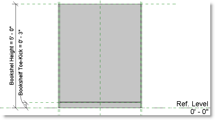
1. Switch to the front view. And move the shelf up 3”. Add a reference plane to the underside of the shelf. Dimension this plane from the reference level and create a parameter named “Bookshelf Toe-Kick”.
2. Use the Array tool with Group and Associate on and Move To set to “Last”. The array should go from the top of the placed shelf to the top of bookcase reference plane.

3. Select the group and associate line with the current number in the array. On the Options bar select

4. Make it an instance parameter and group it under Constraints.

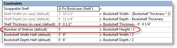
5. In the Family Types dialog add the equation below to place a shelf at about one shelf per linear foot.
6. Flex the family by changing the height of the bookcase, verifying that the number of shelves changes. Also flex the width, depth, and shelf type.
7. If the shelves lean out of plumb, use the Align tool to lock the upper most shelf in place.
Control the Thickness
For this family the user can input the thickness of the bookshelf, this will in turn drive the thickness of the shelves. Let’s create a formula that allows the user to input any thickness they want, however, if the thickness is less than ½” Revit should use ½” anyway. Conversely if the user specifies any thickness greater than 1”, Revit will use 1” only. If the user specifies any thickness in-between, Revit should consider this a fair value and use it directly.
This requires creating an Actual Thickness parameter and a couple of nested IF statements.
1. Create a new instance parameter and name it Bookshelf Thickness Actual. Group it under Constraints.
2. Apply the following equation to the new parameter.
There are essentially two parts to this nested IF statement.
If (Bookshelf Thickness < 0' 0 1/2", 0' 0 1/2",
This first part states that if the Bookshelf thickness is less than ½” use ½” for the Actual thickness. If it is not, refer to the rest of the statement.
if (Bookshelf Thickness > 0' 1", 0' 1", Bookshelf Thickness))
The last part states that if the Bookshelf thickness is greater than 1” use 1”. If it is not, use the Bookshelf thickness.
3. To finish apply the Actual thickness parameter to the constraining dimension instead of the nominal one.
if(BCS Thickness <; 0' 0 1/2", 0' 0 1/2", if(BCS Thickness > 0' 1 3/4", 0' 1 3/4", BCS Thickness))
Using Model Text to Provide User Feedback
Since the user can specify any thickness they want, even if they are wrong, it may be a good idea to provide feedback to the user if the thickness they provide is out of bounds. Model Text will be used for this.
• Place some Model Text on top off the bookshelf and make the text read "XXX".
• Select the Model Text and pick the little square to the right of the Text Parameter in Properties.

• Add a parameter and name it "Thick Condition"
• In the Family Type dialog and a formula as shown below.

• This formula will test to see if the parameters of Bookcase Thickness and Bookcase Thickness Actual are equal. If so the user supplied good data and the model text should read "GOOD". If they are not equal the users supplied bad data and the model text should read "BAD".
Lastly, we only want the model text to display if the condition is "BAD". To do this, create another parameter Called Thick Condition Visible as shown below.

In the Type Parameters dialog, add this formula to the Thick Condition Visible parameter.
Not (Bookcase Thickness = Bookcase Thickness Actual)
This formula returns a true when model text is in a "BAD" condition. When this yes/no parameter is true, it is visible.
The opposite is when the model text is in a "GOOD" condition, the yes/no parameter is false and the Model text will not display.
Important: You must load this family into a project for this to work. The Good and the BAD are visible in the family, but Only Bad is visible once loaded into a project.
No comments:
Post a Comment