
A Word on Styles
If you have used AutoCAD, you may be familiar with a text or dimension style. These styles are used to change the appearance of the text and dimensions. The font, color, height, and width of the text or dimension can all be controlled, but the actual text or length of the dimension does not change. Electrical device styles are used in much the same manner. For example, a duplex receptacle can become a quadraplex receptacle by applying a new style, but the location and connections it has will remain unchanged.
Creating a device.
For this article, I’ll create a 2x4 surface mount fluorescent fixture, but before a new device style can be created, several blocks need to be created. These blocks are used to represent the device for the different perspectives in which it will be viewed. You can create separate blocks for top, bottom, front, back, left, right and models views, but for most electrical devices a model view, a plan view (which can also be used as a reflected view) and an annotation view are all that is required. The model view block needs to be created with 3D solids in order for Collision Detection to function. All the other blocks should be 2D. The Autodesk standard styles have some nice 3D blocks associated with them, and I don’t feel a bit bad about renaming those blocks for my own needs. Do try to adhere to some sort of block naming convention as you go. I created the following blocks for this device. See figure 1.
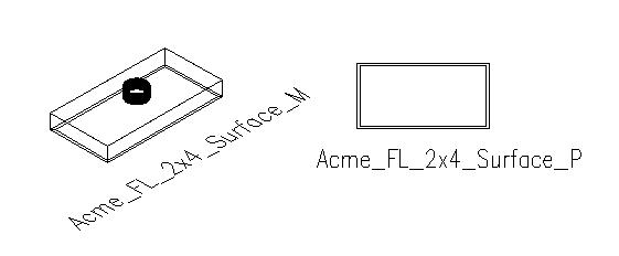
Figure 1
To create a new device style, open the Style Manager by selecting it from the Format pull down menu. Device styles are found under the Electrical Objects heading of the current drawing. Select Device Styles, right click and then select New. This will open the new device style for edit. There are 6 tabs in a device table style. Let’s start at the left and visit each tab that will define our device style.
In the General tab, name this new style “Acme 2x4 Surface”. You may supply a description if you like and attach any notes by selecting the Notes Button. See figure 2.
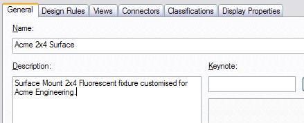
Figure 2
The Design Rules tab allows you to define Type, Layer Key and Wire Cleanup. Select “Lighting” for Type and “LIGHTCLG” for the layer key. If LIGHTCLG is not available choose an appropriate layer key for fixture. The Wire Cleanup option allows you to define how circuited wire is cleaned up with the defined device.
There is no clean up with the None option.
The Bounding Box option will clean up circuits to an imaginary box that encompasses the limits of the devices shape.
Inscribed Circle cleans up circuited wire to an imaginary circle inside a box that encompasses the limits of the devices shape.
Circumscribed Circle cleans up circuited wire to an imaginary circle outside a box that encompasses the limits of the devices shape.
Trace Geometry uses the geometry of the device for wire cleanup.
Choose Trace Geometry for this example. See figure 3.
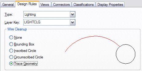
Figure 3
The Views tab is where you define which block to use to represent the device based off the view direction. Select the “Add” button to add a view. In the View Name box, name this view “Model”. Next select the 3d block made to represent this device when viewed from a model perspective (in this case “Acme_FL_2x4_Surface_M) from the View Block list. Select the “Model” Display Representation, then select the “Front”, “Back”, “Left”, “Right” and “3D” View Direction check boxes. See figure 4. The Model view is now configured to show the model block when viewed from any direction other than “Top” or “Bottom” when the Display Representation is Model. See figures 5 and 6 for the Plan view and Reflected view configurations.
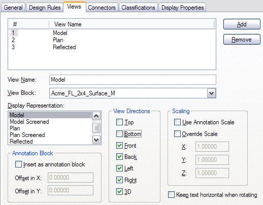
Figure 4
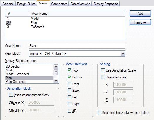
Figure 5
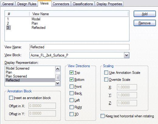
Figure 6
The Connectors tab is where the ABS connection point is defined. If you do not define a connection point, circuits running to the fixture will have nothing to connect to. To set a connection point, assign the System Type to “Power & Lighting”. To center the connection point on the 2x4 fixture, set the Connection Point X value to 2’-0” and the Connection Point Y to 1’-0”. Set the Number of Poles to “
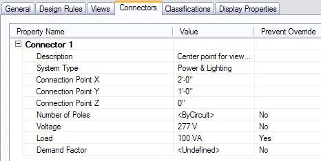
Figure 7
The Classifications tab allows the classification of device styles. Some typical classifications for device styles are “Lighting”, “Receptacles” and “Fire”. Classifications are required for schedules to differentiate this light from anything else a device can be. Select “Lighting” as the device classification. If “Lighting” is not a choice in the Classification list, a classification definition for device type must be added to drawing. Classification definitions are found in the Style Manager under Multi-Purpose Objects. See figure 8.
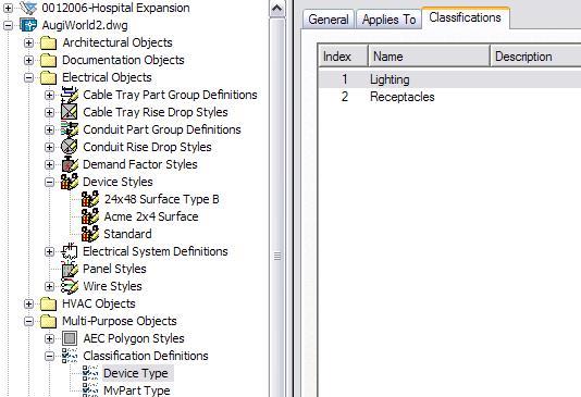
Figure 8
The Display Properties tab allows me to define color, visibility, layer and more for all parts of the device style. Check the “Style Override” check box to open the Display Properties dialog box. Since a layer key has already been applied in the Design Rules tab, overriding layers and colors here is a moot point. Select OK in the Display Properties dialog box, then APPLY and OK to close the Style Manager.
The device is now complete. To insert the device into this drawing select the Add Device tool and change the library to “
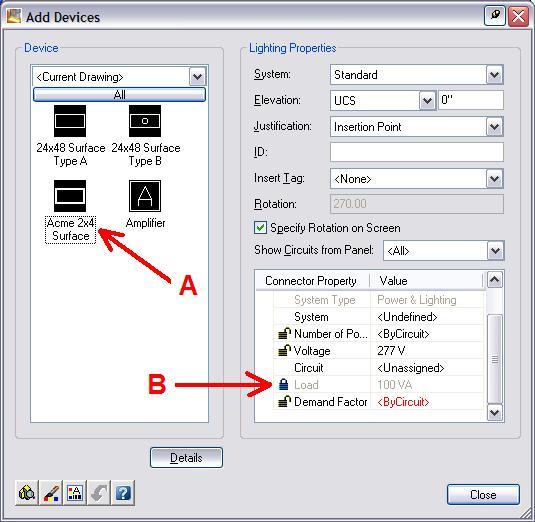
Figure 9
Notice the Acme 2x4 Surface fixture is now listed with a preview image (Arrow A in Figure 9). Note that the VA listed for the device is grayed out (Arrow B in Figure 9). This is because we selected “Yes” to the Prevent Override prompt in the Connectors tab.
Device styles are powerful but can be somewhat complex. Hopefully they are not so intimidating now. As with anything, start simple and build from there. Don’t start from scratch if you can help it. Find a style that is close to what you want to produce, insert it into a blank drawing, select it, right click and pick Copy and Assign to create a copy of the original style that can be freely modified.
3 comments:
Great article.
Do you know of any way to make these devices dynamic at all?
I am trying avoid creating a different device for every size and configuration of light fixtures (1x4, 2x4, 3x4, recessed, surfaced, wallwasher...).
SamAB,
I am kind of embarrassed to say I don't know anymore. Having switched to Revit MEP in 2007, I haven't done much with AutoCAD MEP at all for 4 years. If memory serves, no you can't, but I bet a lot has changed since the last time I did this.
Thanks for your reply.
I found out (after the last post) that you can add PSD info to dynamic block without losing the dynamic aspect of the block. Simply make sure in the Applies To tab of the PSD that you select Block Reference.
This is however, different that a device since it is still a block.
Post a Comment